EP2500 waveform Correction device + SPD for 300-800A panels
The EP-2500, surge protection device + waveform correction device is the industry’s most advanced power quality solution available. The patented circuit of the EP-2500 uses innovative technology to minimize the erratic behavior of sensitive electronic devices, protect the connected equipment, from lighting to motors.
FEATURES AND BENEFITS
– ABSORBS, DISSIPATE & REMOVES with increased capacity
Transient voltage surges and spikes
Frequency Noise between 3kHz-1MHz
Ring waves
– Does NOT shunt energy to the ground
Uses self healing TMOV and tank circuit to self dissipate energy in the form of heat
– Provides 80kA per mode single-pulse surge current\
– Reacts to transient in nanoseconds
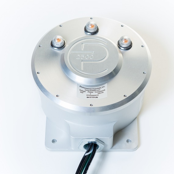
– Status LED Indicators
– 5 Year Warranty
GENERAL SPECIFICATIONS
OPERATING FREQUENCY: 45 – 65 Hz
FREQUENCY ATTENUATION: -20 dB/decade roll-off starting at 2.5 kHz
MAX SURGE CURRENT: 80 kA per mode
MCOV: 20% above rated voltage
SAFETY APPROVALS: UL 1449 4th Edition Type 2 SPD, CSA std. c22.2 No. 8-2013 Ed 5
SAFETY RATINGS: Fire Rating 94V-0
OPERATING ENVIRONMENT: Approximately -25 C to 65 C
COMPLIANCE: NEMA LS-1, NEC Surge Suppression Standards, Electrical Notice 516
CONNECTION: Wire leads. Size: 10 AWG Length: 3’
MATERIALS: Aluminum Housing, LED Indicator Lamps, 10 AWG 600 V rated Wire. Circuit encapsulated in epoxy to retain integrity of circuitry in failure mode.